Breaking The Size Barrier
How I Turned Large Pieces on my Sherline Mill
By Charlie Lear, Melbourne, Australia
Wm. Dubin started it all. For those who don't frequent the Sherline or Model Engineering internet mailing lists, he is an incredibly talented artist who creates kinetic sculpture in the mechanical engineering field. To be amazed and delighted, check out
Wm.'s website when you've finished here.One thing that sets Wm. apart from the crowd is that all his work is done on a standard Sherline lathe and milling machine. In November 2001, Wm. asked how he could machine large flywheels on his Sherline. The majority of the responses were to buy or borrow time on a bigger machine. I got to thinking.
The headstock on a Sherline lathe rotates around a central pivot for taper turning. When not rotated, it is located parallel with a rectangular steel key. Instead of putting in riser blocks, or cutting a lathe bed in half to make a pit lathe, what if we turned the headstock 90 degrees, and mounted the lathe on the front of the workbench?
That way, any diameter stock could be turned, subject to how far you could crank the cross slide out of the way down the bed.
A few moments thought dismissed the idea. For a tool to bear on the overhung work, the cross slide would have to be at the extreme of its outboard travel and the setup was inherently unstable. All the turning forces would be deflecting the tool upward (we'd have to mount the tool upside down, as in the normal direction of rotation we'd be working on the "back" of the workpiece) and this would translate to a twisting force along the bed.
The Sherlines are remarkably well designed and very rigid when operated within their limits, but this went well beyond that. Wm. is interested in turning cast iron flywheels and as I mentioned in an email to him, rigidity is the key.
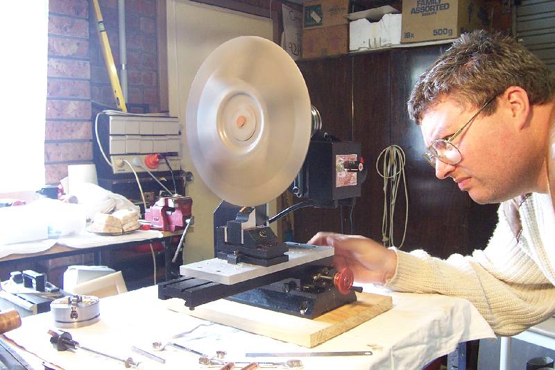
Where this setup WILL come in handy is where you want to mount a sanding disc or to hand turn a wooden bowl, or similar, but those don't involve stressing the end of the bed.
OK, so the lathe is out… what about the mill?
If we put a faceplate or lathe chuck on the mill spindle, we are limited to swinging a workpiece diameter of twice the throat depth (distance from the vertical slides to the centre line of the spindle). If you have the mill riser blocks installed, you can swing a larger diameter, but if you don't? In each case the turning tool would be fastened to the mill table.
Yes, it is practical, and it is an easy option. But what about something larger? What if we turn the mill headstock 90 degrees, so that the spindle is horizontal, and the workpiece is offset from the vertical ways? We are limited in diameter to twice the maximum height from a mounted tool to the centre line of the spindle. There are obvious limitations regarding workpiece rigidity, workholding and minimum rotational speed, but this isn't a production environment. We want to be able to make a once-in-a-blue-moon job, we aren't too concerned about how long it takes if we have to use very fine cuts to avoid upsetting the machine.
Can it be done?
YES IT CAN. I WENT OUT TO MY WORKSHOP AND DID IT. HERE'S HOW!
(Please wait for the page to load. There are around 1MB of images, cut down to suit an 800x600 screen. If you need a closer look at a setup, or higher detail, email me with the picture name and I'll email you back the 1800x1200 original.)
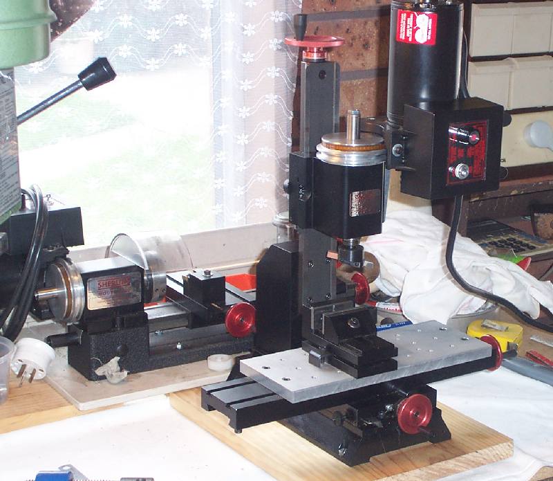
This is my standard 4100 lathe and 5100 mill. The last job I did on the mill was to flycut a base casting for a small steam engine. I use the tooling plate as I feel it gives greater rigidity and vibration damping. So far, it hasn't got in the way and when it does, I'll simply take it off.
The machine vice has already been set parallel to the X (crosswise) axis of the machine.
Let's get this thing converted into a lathe!
First job is to drop the speed to the lower setting. The small pulley on the motor and large pulley on the spindle gives lower speed and higher torque, both required for the work we are going to do.
I removed the flycutter by holding it in one hand and turning the drawbolt with a ring spanner. It pays to buy a single, good quality spanner to fit the drawbolt. Crescents work, but you will either round off the corners of the bolt or it will slip and you'll whack your hand on the vertical ways. I know it isn't a proper job until blood's been spilled, but there's no point tempting fate. I undid the bolt a couple of turns and gave it a gentle tap with a plastic faced hammer. Two taps was enough to drop the flycutter out of the taper. Do not use force or you will damage the spindle bearings.
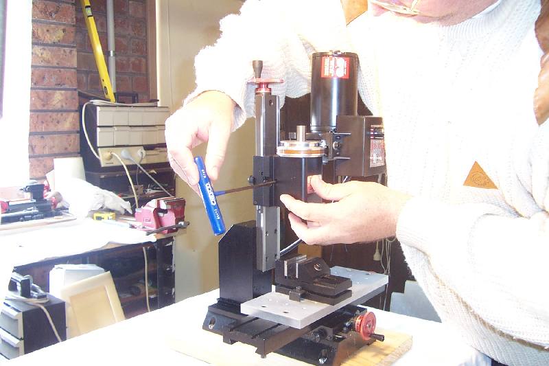
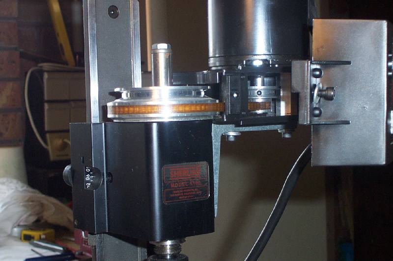
Next we need to rotate the headstock, by unlocking the clamp screw shown and removing the locating key. The T-driver is worth its weight in gold - it is a lot easier on your hands and patience when dealing with all the capscrews on a Sherline, and the handle makes a dandy soft hammer for gently tapping workpieces or accessories into alignment.
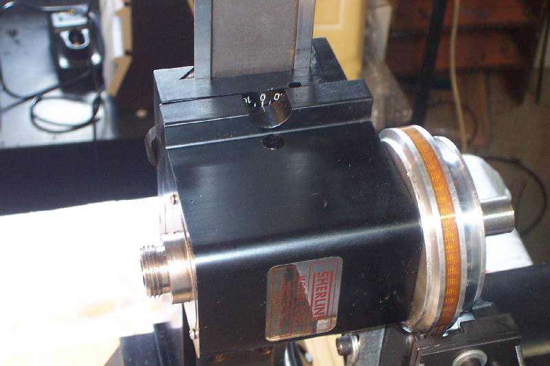
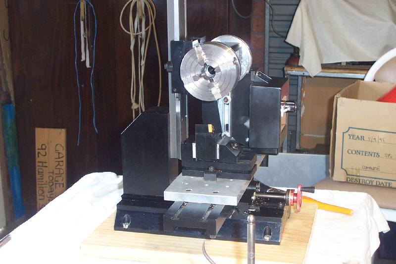
Here's the headstock rotated 90 degrees and locked in place. The markings line up but the base is certainly not square. Do I trust the machining of the base, or the marks engraved on it? I'm not qualified to tell. What we need to do now is set the spindle truly horizontal, within reason.
Precision is often a state of mind, more than the on-paper specifications of the machine or the ability of the operator.
Joe Martin, owner of Sherline, designs and builds the machines to turn or be aligned within a thousandth of an inch or two. If we had a 1 Morse taper ground test bar and a dial indicator reading in ten thousandths of an inch, we could get this spindle horizontal to the table within maybe half a tenth, if we had all day and didn't mind the setting getting screwed up with temperature changes or tightening up adjustments.
I don't have a test bar and didn't want to spend all day. I've got a couple of good dial indicators but in this case I didn't need them. A standard surface gauge worked well.
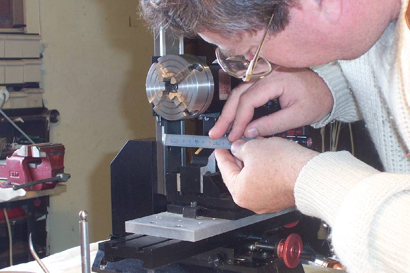
My small 3-jaw chuck is quite accurate for most purposes. I chucked a length of 8mm diameter ground steel bar, put the point of the surface gauge next to it, and rotated it to check for runout. Very little discernable runout at all, a most satisfactory state of affairs.
What you are looking for is for the tiny gap between the point and test piece to stay constant. With more rigidity in the scriber setup, it is possible to rotate the test piece against the scriber tip and mark a faint line all round. The width of the line indicates runout - the wider (and therefore deeper) the line, the closer that side is to the scriber.
Next I traversed the table (with the surface gauge) away from the chuck. The scriber got closer the further away it went, so I slackened off the headstock locking screw to adjust it. Of course the weight of the motor pulled it down… so back to the start, and each time it needed adjusting I barely slackened the screw and tapped the side of the headstock with the T-driver handle to shift it a smidgen (== half a gnat's whisker).
After five iterations I was quite happy with the setting. The bar was as horizontal IN RELATION TO THE TABLE as it was going to get, without going to extremes. We're only turning the periphery of a flywheel, if we wanted to do a turbine impeller we wouldn't be doing it on this machine!
The proof of the pudding was that the headstock was lined up with neither the base, nor the graduations. This indicates that the vertical vee ways are leaning slightly - I'll shim that out when I return the mill to its normal configuration. By traversing the table, instead of just swinging the surface gauge on its base, we are making sure that any slight inaccuracy in the surface of the mill table or tooling plate is neutralised.
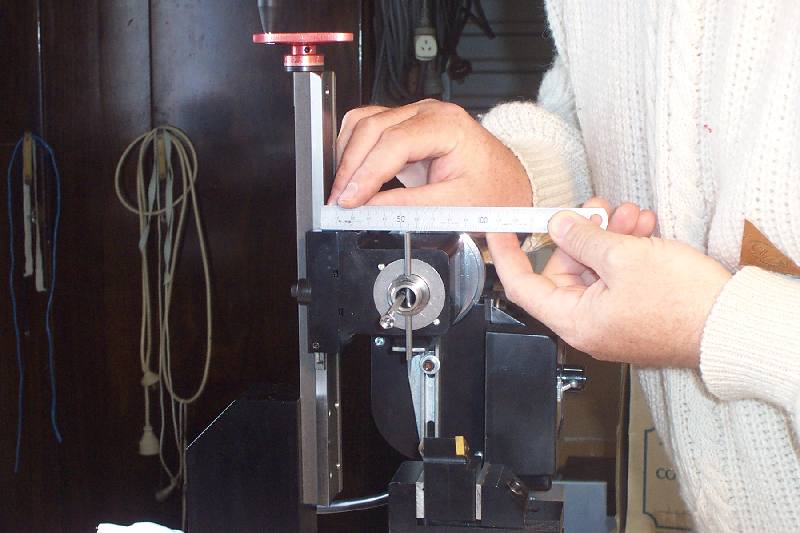
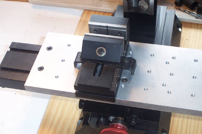
With the 7610 carbide tool block held squarely in the machine vice, we need to set it to "centre height" in relation to the spindle. I used a jewellers screwdriver to jam a tommy bar in the spindle cross hole and put an engineers square against the vee ways. A six inch rule held against the square gave me the measurement at the top of the tommy bar. I repeated the measurement at the bottom end, without moving the spindle. The average of the two readings, less half the diameter of the tommy bar, is the distance from vee ways to the centreline of the spindle - in this case as close to 55mm that it doesn't matter.
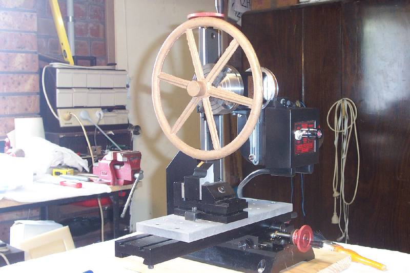
Here's the setup, ready to cut metal. The spindle is horizontal, the tool is set to exactly 55mm from the vee ways, and the more astute among you will have noticed the Deliberate Misteak.
Yes, dear readers, I'd forgotten what way the spindle turned. It's anticlockwise and I'd done a brilliant job of setting the tool up for clockwise turning. Argh…
With the tool block turned around, I was able to put the end of the six inch rule directly on the vee and move the table to exactly 55mm. Think of the tool forces when the machine is cutting - in this case it will be from the rear of the machine to the front. Because of this I moved the table out too far, and brought it back in to 55mm. That way there will be no backlash when the tool starts to cut. When this measurement has been set DO NOT TOUCH the Y axis handwheel again.
Here's the 8-1/2" diameter gunmetal (bronze) casting I wanted to use as a test piece. I specifically did not want to do any more than take a light surface cut over the periphery of the wheel. When I machine it "for real" it will be on a faceplate on a larger lathe. The job today was to prove the concept and show that a Sherline mill can be used to turn a large diameter. The pic shows the casting with the rough blobs filed off the chucking piece in the centre.
The casting is now mounted in the mill. I used the 4-jaw chuck to eliminate much of the wobble in the off-centre chucking piece, and the extra jaw provides much better grip. The tendency for a workpiece of this type is to work its way out of the chuck due to the levering action of the tool forces at the periphery against the much smaller diameter of the chucking piece.
So! Would it work? Or would I bust the tool or send the flywheel flying to the other side of the shop?
You bet it works!!!
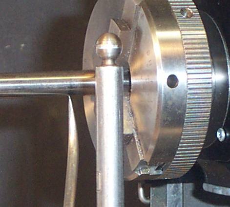
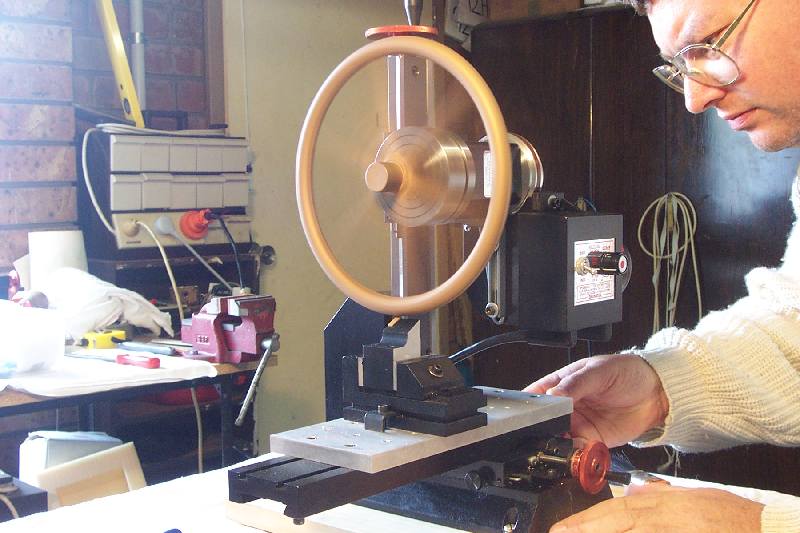
I "put on" the cut by lowering the headstock on the Z axis too far, then bringing it back up to eliminate backlash. Because my mill is a couple of years old, it doesn't have the locking lever on the Z axis leadscrew. I adjust it reasonably tight to compensate. The photo shows the tool taking the first scrapes at just above the minimum speed of the motor. There isn't a lot of torque available at this low speed, and any attempt to "hog" the cut stalled the whole deal. But by using a fine feed on the X axis and not being too ambitious with the cut, I ran three successful traversing cuts across the rim.
The flywheel "dinged" like a bell every revolution when the tool made contact. If the "ding" got too much, the vibration would show as chatter marks. I didn't see any but it should be possible to rig up something like a rubber roller on the top of the flywheel to damp out the vibration if required.
Being sand cast, the flywheel has a hard outer "skin" which is very abrasive. The carbide tool successfully skimmed through it, but it would destroy a high speed steel tool fairly quickly.
For machining a cast iron flywheel, or if I was machining this one for real on the Sherline, I would file off the hard skin all the way around. An hour with the file would save a lot of machining time and tool replacement!
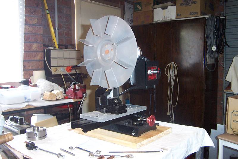
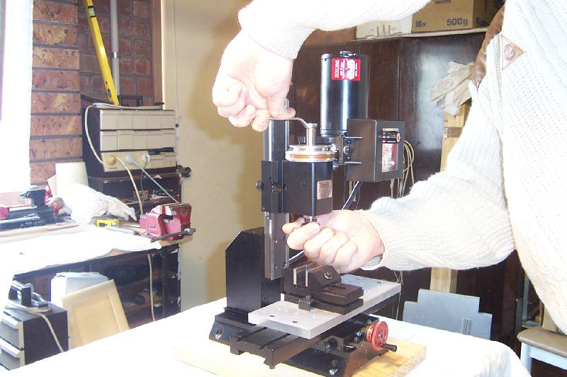
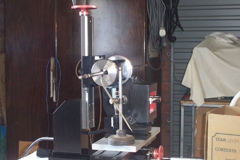
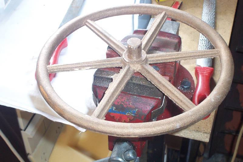
Since I was on a roll, I decided to play with the setup. I took off the four jaw and put the three jaw chuck back on. I had a diecast fan impeller, 10-1/4" diameter. It is screwed to a spigot which is setscrewed to a motor shaft. The casting has "crept" with age and it makes an annoying scraping noise against the housing. Could I true the edge and back? Lunch could wait!
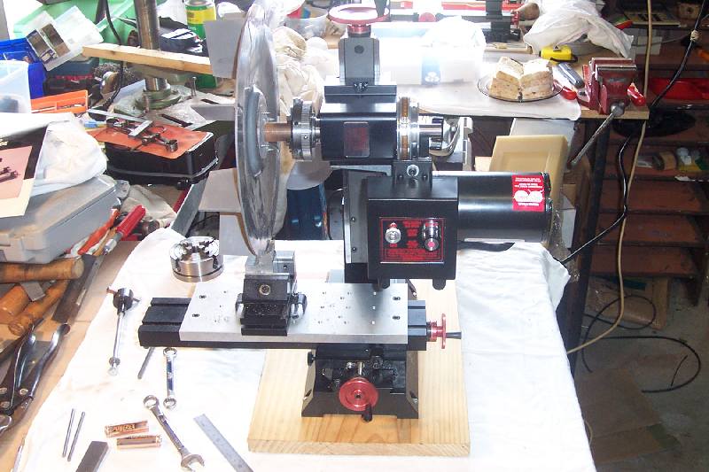
This photo shows the total overhang of the workpiece and offset of the tool. In this case the tool is offset approximately four inches from the centre line of the Z axis vee ways. Obviously the closer the workpiece can be mounted to the spindle nose the more rigid the whole setup will be. I stress that this example was using very light cuts at just over minimum speed in order to true the impeller rim. I would not take normal cuts with this sort of overhang and using the three-jaw chuck.
If you are thinking that you will be doing more than the occasional job in this manner, I'd suggest making a larger than standard faceplate, perhaps by bolting a larger disc to a standard Sherline faceplate, or using an aluminium sanding disc plate. I wouldn't use a cast iron faceplate from a larger lathe as I believe the unsupported weight would not be wonderful for the headstock bearings.
The overhung weight of a flywheel is acceptable in my opinion as this is something you'd only do once in a blue moon. If you're going to do it more often, buy or borrow time on a bigger lathe!
Yes, I could!
All in all the exercise was very informative and worthwhile. I hope the information is helpful and encourages you to have a go yourself! Do not leave your lunch in line with the rotating workpiece, though, unless you like picking out the crunchy bits.
Regards
Charlie Lear
18 November 2001