This tutorial illustrates how to make what I call a “scalebox” to help reference while building a locomotive or other object in gMax or Gmax. Many locomotives available where made using this method and it is the standard used to build things quicker and more accurately from diagrams. The key to all of this is starting out with an accurate diagram or drawing. Once that is achieved, anything can be made by virtual 3d "tracing" of the reference image.
NOTE: You must have a basic understanding of the Auran provided Content Creation Guide which is available here. You must also be proficient in your selected Image Editor and 3d Modeling programs.
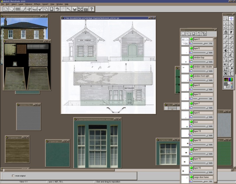
First thing you need is an accurate drawing of your object. In this example I am using my Sandy River Forney #5 diagram. It has been cropped and cut into 3 separate images for use in making the scale box.
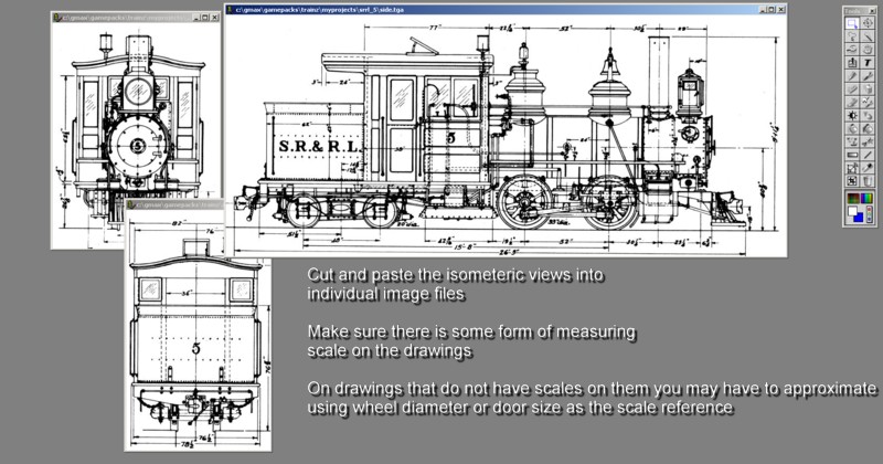
The figure is pretty self explanatory. You MUST have some sort of scaling drawn on the finished images for accuracy. Some images I have used do not have scales on them so I had to add them with a ruler. A little work here before you scan the diagram will pay big dividends later. Make sure it is clean also, you can use your photo editor to clean up the images as well as add scaling grids and lines if needed.
Hop into your modeling program and make four single segment planes in each of the cardinal isometric views as seen in the figure. – I named them: side, front, rear and top. Then make the “scalebox” which is nothing more than a transparent box at the extreme dimensions of your object. This will help you align the drawings once they are applied to the planes. My original drawing had all the measurements on it so this was easy, I just keyed in the measurements and plopped the box in place. (notice that I left the “top” plane off to the side, this I do so I can build stuff on top of it and then move the items over to the main mesh area like frames and pilots)
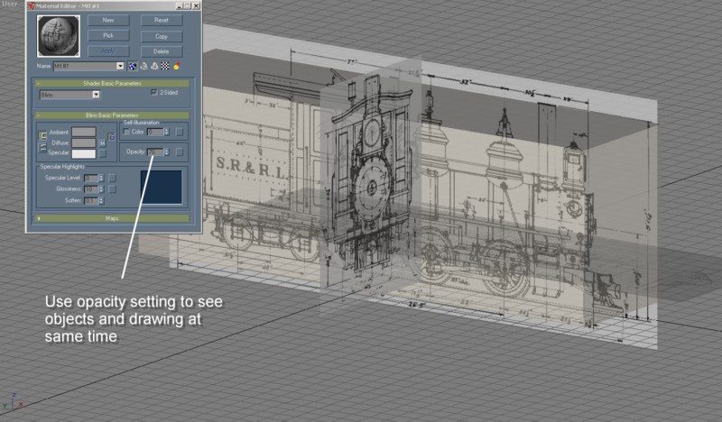
Now you apply your texture images you made earlier to the appropriate planes. I left the ‘front’ and ‘rear’ planes single sided so that I do not see them from the opposite angle. The ‘side’ plane material has been made 2 sided so I can see it from both sides. You can use the opacity option in Material Editor to adjust the transparency of the image materials so you can still see stuff while you’re working on it.
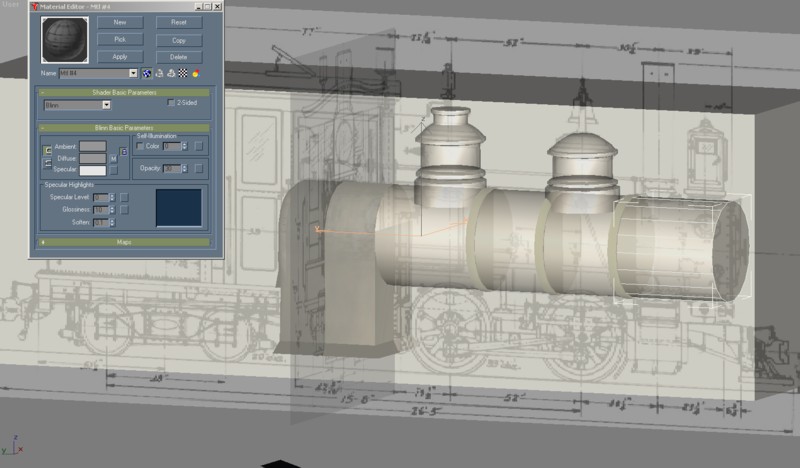
Here you can see how the transparency of the objects and the diagram planes can work together when building. Later it gets more difficult to see what you are doing and look at the diagram at the same time, I usually keep a copy of the diagram on my desk or on a separate file I can open while modeling for reference.
You can continue on this way with the scalebox as your primary reference through the creation of the model. Bogeys can be made here as well and saved as separate files later once all the mesh is completed
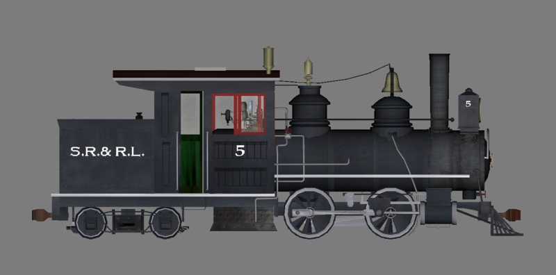
Compare the finished model here with the diagram at the beginning of this page and you can see how useful this technique is.
Of course texturing and mapping is an entirely different subject. Happy modeling.